Connectors and Cabling for UHF Base Stations
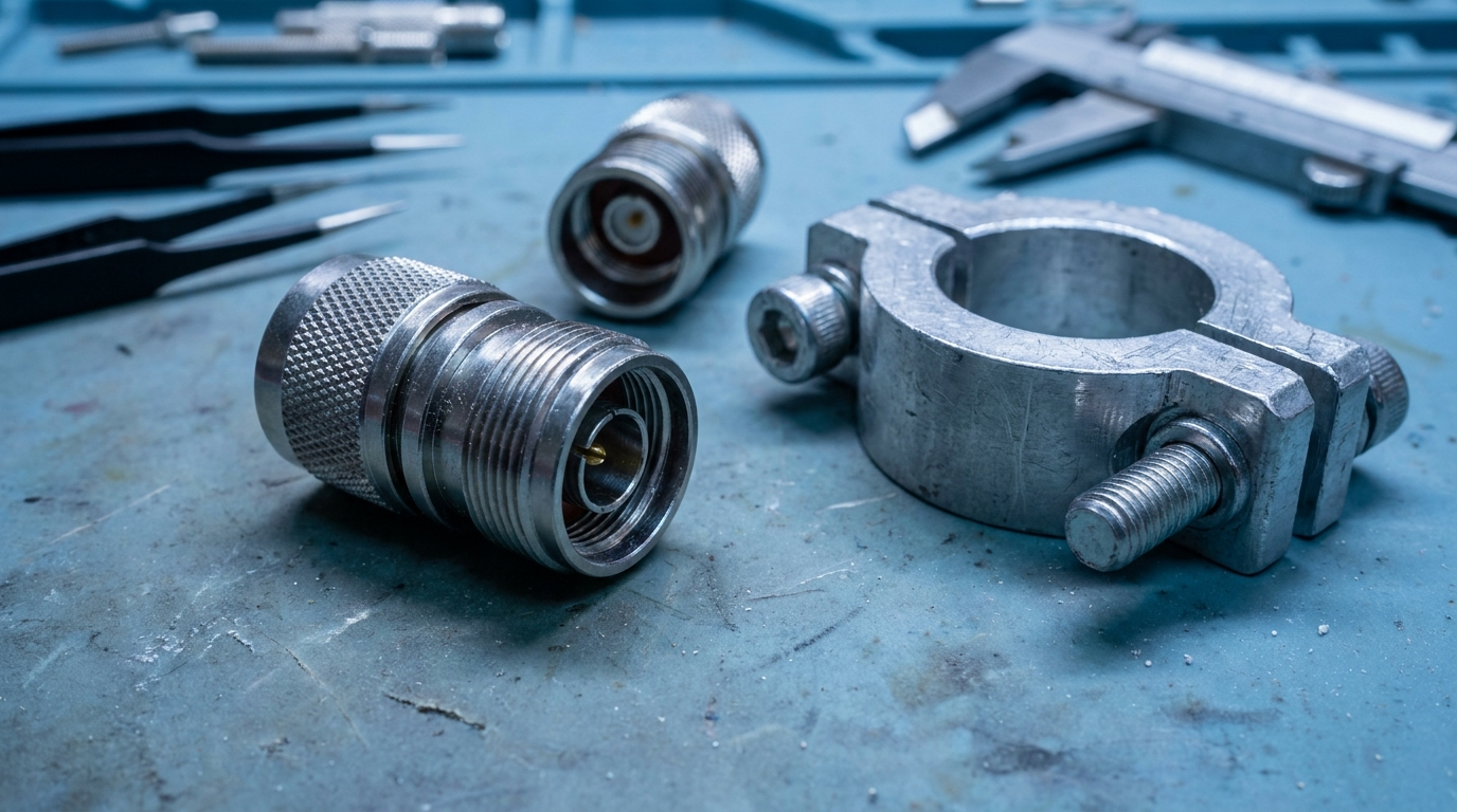
The weakest link is almost always a connector
Every antenna datasheet gives you specified gain and VSWR values measured under ideal conditions. On site, the real performance of a UHF base station install is limited by the cable run and the connectors. It is worth specifying those with at least as much care as the antenna itself.
Cable selection: the short version
For UK UHF base station work, cable choice usually comes down to a balance of loss per metre, flexibility and cost. A working shortlist for typical public safety and commercial UHF installs:
- RG213: Standard 50-ohm coax, widely available, adequate for runs under 20 metres at UHF. Loss around 0.2 dB/m at 450 MHz.
- LMR400 or equivalent: Low-loss cable suited to runs of 20 to 40 metres. Loss around 0.09 dB/m at 450 MHz. Stiffer than RG213 but manageable in most riser installations.
- Heliax (FSJ4 or similar): For runs over 40 metres, or where feeder loss budgets are tight. Substantially lower loss but less flexible and more expensive to terminate.
As a rough rule, losing more than 3 dB in the feeder starts to erase the advantage of a higher-gain antenna. Run your numbers at the top end of the UHF band where loss is worst.
Connector choices
For UHF base installs, the usual connector options are:
N-type
The standard for professional UHF base station work. Rated to 11 GHz, robust, and straightforward to weatherproof. Use N-type at both ends of the feeder run unless the radio or antenna specifies otherwise.
7/16 DIN
Used where low PIM and high power handling are required, typically in multi-operator base stations and high-power broadcast feeders. Larger and heavier than N-type, but significantly lower intermodulation and higher power rating.
TNC and SMA
Not suitable for permanent outdoor base station feeders. TNC is used on some radio equipment ports; if your radio presents a TNC, use a short TNC-to-N pigtail at the equipment end and N-type for the feeder run. SMA is an indoor, low-power connector only.
Weatherproofing
UHF connectors fail more often from water ingress than from poor termination. A reliable outdoor seal usually follows the same sequence: self-amalgamating tape applied from the connector body outward, then an outer layer of UV-stable weatherproofing tape or a proprietary adhesive boot. Do not shortcut this. A dry connector will outlast the antenna; a wet one usually fails within 18 months.
On rooftop installations, loop the cable in a drip loop below the connector before it enters any penetration. This prevents water tracking along the outer jacket into the connector body.
On-site quality control
Check VSWR at commissioning
Measure VSWR at the radio port before going live. A good feeder with properly terminated connectors should add no more than 0.1 to 0.2 to the antenna's specified VSWR. If you see a large discrepancy from the datasheet figure, the problem is almost always a connector, not the antenna.
Torque to specification
N-type connectors should be torqued to 1.4 Nm (12 in-lb). Over-tightening distorts the connector body; under-tightening introduces impedance discontinuity and intermittent contact. Use a torque wrench, not a spanner by feel.
Document the baseline
Record the commissioned VSWR figure at the top, bottom and centre of the working band. Photograph the cable run, connector positions and weatherproofing. This baseline lets you identify connector degradation at the next maintenance visit without guesswork.
Ordering from Renair
We hold UK stock on the most commonly specified cable, pigtails and connectors for UHF base installs. If you are scoping a new project and want a bill-of-materials check before you order, send the antenna model and the run details to sales@renair.co.uk and we will come back with a ready-to-order parts list.
Related products
Related reading
Understanding the Innovative Technologies Behind Our Antenna Solutions
At Renair, we utilise cutting-edge technology to design antennas that excel in performance and reliability. Our manufacturing process incorporates rigorous testing to ensure each product meets the highest standards. This commitment to quality guarantees that our antennas provide seamless connectivity for a variety of applications.

VHF vs UHF Antennas: Which Do You Need?
The difference between VHF and UHF antennas in plain English: range, terrain, building penetration, antenna size and which sectors use which band.

Do You Need a VHF Radio Licence in the UK? Ofcom Rules Explained
Which licences you need to use a marine VHF radio in the UK: the Ofcom Ship Radio Licence, the Ship Portable Radio Licence and the operator's certificate, plus what changes for land-based VHF.

UK Airband Frequencies: A Guide for Airfields, Flying Clubs and Listeners
How the UK aviation VHF airband works, from 118 to 137 MHz and 8.33 kHz channel spacing to the emergency frequency, plus how to choose an airband antenna for an airfield or ground station.
Our Customers
Lorem ipsum dolor sit amet, consectetur adipiscing elit.
“The team at Renair is always ready to assist, providing expert advice and quality products.”


“Renair’s bespoke antenna solutions have significantly enhanced our system performance.”

“We rely on Renair for all our antenna needs. Their products and service are consistently excellent.”

“Renair’s team provided exceptional support throughout our project, ensuring seamless integration.”

“The quality of Renair’s antennas is unmatched. Our communications have never been clearer.”

“Renair’s customer service is top-notch. They promptly addressed our queries and provided tailored solutions.”


Get in Touch with Us
Contact Renair today for inquiries, partnerships, or to learn more about our solutions.